35+ blocking oscillator circuit diagram
You said I can add 022 ohm resistors in parallel with the emitters of each transistor. The entire cell phone signal jammer circuit can be powered up using a 9V battery.

How A Blocking Oscillator Circuit Works Circuit Projects Electronics Projects Electronics Circuit
They are widely used in many electronic devices ranging from simplest clock generators to digital instruments like.
. I used 1 ohm resistors at the. For any signal jammer circuit there are three main parts in the circuit and when combined together the output of that circuit will work as a jammer. Oscillators convert direct current DC from a power supply to an alternating current AC signal.
We would like to show you a description here but the site wont allow us. Updated 2020-08-27 Introduction This is an open source Arduino based CW Morse Code keyer with a lot of features and flexibility rivaling commercial keyers which often cost significantly more. The Switch S1 is.
When the current flowing through the coil changes the time-varying magnetic field induces an electromotive force emf in the. An inductor typically consists of an insulated wire wound into a coil. The output of oscillator is fed to amplifier so that loses in transmission can be compensated.
This RF circuit amplifies the signal generated by the tuned circuit. That is my circuit. The cylinder continues its downward motion and comes in front of LDR2 blocking its beam and lowering its resistance this stops the transistor from conducting such that the potential at pin14 of the IC.
High frequency carrier signal is generated in oscillator. These three main circuit parts are. HARDWARE TESTING 31 6.
These 3 circuits when combined together form an efficient cell phone jammer circuit. The output voltage of a oscillator is held constant by voltage stabilizer. The 5th circuit diagram below shows an industrial motion sensor circuit using a couple of LDRs an IC and a few other passive components.
BLOCK DIAGRAM OF THE PROJECT 8 A TYPICAL TRANSFORMER 12 BLOCK DIAGRAM OF VOLTAGE REGULATOR 14 RC FILTER RECTIFIER 18 TRANSISTOR 19 LED 20 BRUSHLESS DC. RF amplifier circuit comprises of the transistor Q1 capacitors C4 C5 and resistor R1. An electronic oscillator is an electronic circuit that produces a periodic oscillating electronic signal often a sine wave or a square wave or a triangle wave.
MEDICAL APPLICATIONS 34 9. FUTURE PROSPECTS 33 8. As I said I am trying to increase the total power.
Voltage Controlled Oscillator. Oscillator can be crystal oscillator with which operation for a particular bandwidth can be achieved. An inductor also called a coil choke or reactor is a passive two-terminal electrical component that stores energy in a magnetic field when electric current flows through it.
6 LIST OF FIGURES PAGE NO. A DHCP server typically runs in a router and offers IP addresses to DHCP clients. The code can be used with a full blown Arduino board or an AVR microcontroller chip can be programmed and used directly in a circuit.
Dynamic Host Configuration Protocol DHCP The dynamic host configuration protocol DHCP is the application responsible for requesting and offering IP addressesA DHCP client automatically requests an IP address from a DHCP server when a network is detected. Is that what you mean as in my circuit.
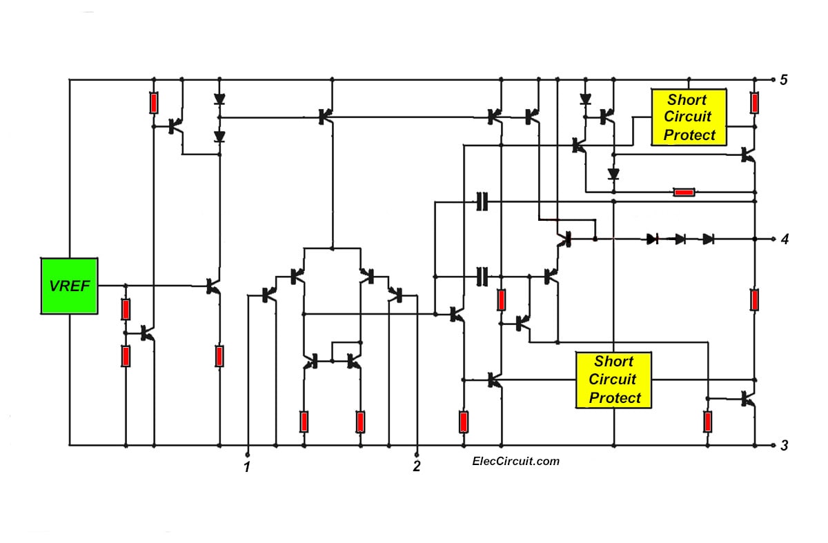
Tda2050 Amplifier Stereo 35w 75w
Tda2050 Amplifier Stereo 35w 75w
What S A Schematic Diagram For The World S Best Efficient Joule Thief Circuit Quora
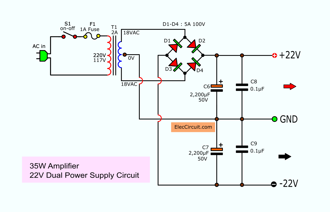
Tda2050 Amplifier Stereo 35w 75w
What S A Schematic Diagram For The World S Best Efficient Joule Thief Circuit Quora

How Can We Increase The Efficiency Of Peltier Modules Tecs Can A Joule Thief Circuit Be Helpful Quora
How Can We Increase The Efficiency Of Peltier Modules Tecs Can A Joule Thief Circuit Be Helpful Quora
Do Bits At 0 Use Less Battery Than Bits At 1 All Other Things Being Equal Quora

This Is A 1 2 Volt Single Transistor Flyback Joule Thief Circuit That Features A Third Coil With Joule Thief Electronic Circuit Projects Electronics Basics

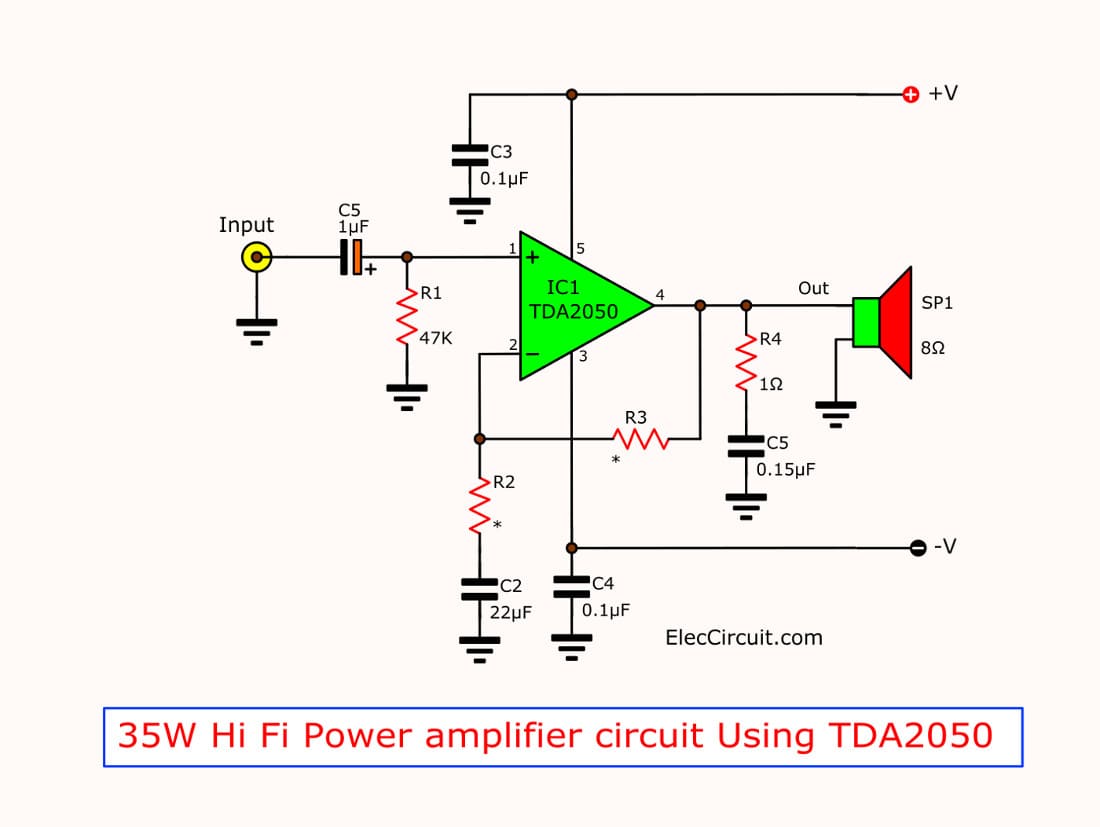
Tda2050 Amplifier Stereo 35w 75w

Voice Switch Circuit Diagram Circuit Diagram Voice Activated Switch Voice Switch Circuit Diagram Circuit Diagram Voice Activated Circuit

Mosfet Based Joule Thief Steps Up Voltage Edn Joule Thief Power Supply Circuit Free Energy Generator
Tda2050 Amplifier Stereo 35w 75w

Rccoupled Amplifier Coupling Is The Most Widely Used Method Of Coupling In Multistage Amplifiers Amplifier Transistors Circuit Diagram

Photo Of Transistor Blocking Oscillator Driving A White Led The Inductor Is Wound On A Rusty Flooring Nai Led Electronics Mini Projects Electronic Engineering
What S A Schematic Diagram For The World S Best Efficient Joule Thief Circuit Quora
What S A Schematic Diagram For The World S Best Efficient Joule Thief Circuit Quora